

Standby Generators
 Aug 14th 2021, 7:48 pm
#31
Lost in BE Cyberspace

Joined: Nov 2007
Location: Bay Area, CA
Posts: 13,111


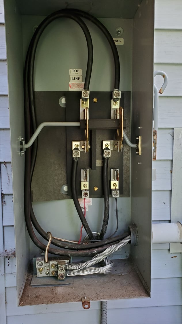
Looks very straight-forward, but .... aren't the two big fat black wires at the top the two 'phases' of the three-phase utility supply, whereas, the red/black at the bottom represent the single-phase from a generator? Is that kosher? Or - noticing the sticker 'LINE' above the 'left' wire, perhaps the left wire is one phase from the utility, while the right-hand wire is 'neutral'; that would make more sense, in terms of having the generator 'red' wire going to the 'LINE' feed, and the black wire going to the 'neutral' feed. But if that is the case, what happens to the 'other' phase coming into your home? Most homes have two phases coming in from the utility. Are you simply feeding the generator into one of the two phases, and then accepting that only 'half' of your home breakers are going to be 'life' in an outage?
Also - is this a simple example of a 'transfer switch'? Looks like it to me!
Also - is this a simple example of a 'transfer switch'? Looks like it to me!
 Aug 14th 2021, 11:39 pm
#32
DE-UK-NZ-IE-US... the TYP
Joined: Mar 2010
Posts: 2,855
Aug 14th 2021, 11:50 pm
#33
Joined: Apr 2012
Location: CT
Posts: 33,495
we have never used it but we are looking at getting a new generator so I would want to swap that out at the same time. The rest of it seems ok.
Aug 15th 2021, 8:21 pm
#34
Joined: Apr 2012
Location: CT
Posts: 33,495
Looks very straight-forward, but .... aren't the two big fat black wires at the top the two 'phases' of the three-phase utility supply, whereas, the red/black at the bottom represent the single-phase from a generator? Is that kosher? Or - noticing the sticker 'LINE' above the 'left' wire, perhaps the left wire is one phase from the utility, while the right-hand wire is 'neutral'; that would make more sense, in terms of having the generator 'red' wire going to the 'LINE' feed, and the black wire going to the 'neutral' feed. But if that is the case, what happens to the 'other' phase coming into your home? Most homes have two phases coming in from the utility. Are you simply feeding the generator into one of the two phases, and then accepting that only 'half' of your home breakers are going to be 'life' in an outage?
Also - is this a simple example of a 'transfer switch'? Looks like it to me!
Also - is this a simple example of a 'transfer switch'? Looks like it to me!
[edit] Yeah.. Simple (old) transfer switch.
Aug 16th 2021, 3:28 pm
#35
DE-UK-NZ-IE-US... the TYP
Joined: Mar 2010
Posts: 2,855
It’s interesting what others said about not running AC. I was not sure ours would work, we have a gas stove and dryer, so when I have run this I did not really shut any thing off. I can definitely hear it work harder once the AC comes on, but it worked and managed to run that and everything else. I brought a smaller LPG unit for my other house, but it’s only 120v so I don’t think it can run my well pump… back to looking at solar and a power wall or 2 (assuming that can get through the night).
 Aug 16th 2021, 4:02 pm
#36
BE Commentator
Joined: Feb 2010
Location: Los Angeles, California
Posts: 8,424
Looks very straight-forward, but .... aren't the two big fat black wires at the top the two 'phases' of the three-phase utility supply, whereas, the red/black at the bottom represent the single-phase from a generator? Is that kosher? Or - noticing the sticker 'LINE' above the 'left' wire, perhaps the left wire is one phase from the utility, while the right-hand wire is 'neutral'; that would make more sense, in terms of having the generator 'red' wire going to the 'LINE' feed, and the black wire going to the 'neutral' feed. But if that is the case, what happens to the 'other' phase coming into your home? Most homes have two phases coming in from the utility. Are you simply feeding the generator into one of the two phases, and then accepting that only 'half' of your home breakers are going to be 'life' in an outage?
Also - is this a simple example of a 'transfer switch'? Looks like it to me!
Also - is this a simple example of a 'transfer switch'? Looks like it to me!
So, the power drop consists of the two black lines of 120 v each and the bare ground/neutral wire. I see that there appears to be a grounding cable coming out of the bottom. I presume that the conduit to the right hooks up to the meter.
This installation strikes me as a “Mickey Mouse” conversion of the house cutoff into a transfer switch. Betcha it ain’t legal.
Aug 16th 2021, 5:18 pm
#37
Lost in BE Cyberspace
Joined: Nov 2007
Location: Bay Area, CA
Posts: 13,111
Just upgraded the service on my house. Department of Water & Power did a “meter spot” and our 1938 power drop had to be relocated. So new main panel on north side of house with old panel on south side converted to a sub panel. I like to have basic knowledge of my house’s systems.
So, the power drop consists of the two black lines of 120 v each and the bare ground/neutral wire. I see that there appears to be a grounding cable coming out of the bottom. I presume that the conduit to the right hooks up to the meter.
This installation strikes me as a “Mickey Mouse” conversion of the house cutoff into a transfer switch. Betcha it ain’t legal.
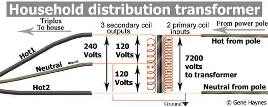
I found this diagram online that really helped: Note, the 'flow' is from right to left (utility pole on the right, house on the left):
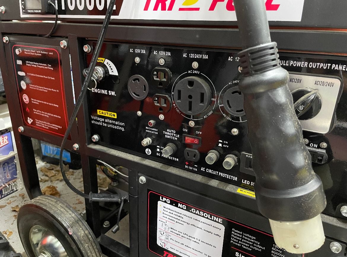
The question I still have for Nutek is what is the voltage generated by his generator; if his generator is 240V, then that makes sense - that is, the red and black wires coming into his 'transfer box' at the bottom are each 120V relative to ground, or 240V relative to each other. If the generator is only 120V (which I originally assumed when I replied above) then I don't understand how it could work. I've asked Nutek for more details by PM. Hopefully we can clarify here when resolved!
Aug 16th 2021, 5:42 pm
#38
BE Commentator
Joined: Feb 2010
Location: Los Angeles, California
Posts: 8,424
I need to clarify / fess up that I was completely wrong above - typical houses do NOT get 'two phases' fed to them from the utility; they get two 120V lines, which are fed from a center-tapped winding on a transformer at/near the utility pole, which is fed by a single-phase of the utility source; correctly referred to by Nutek as 'split phase'.
I found this diagram online that really helped: Note, the 'flow' is from right to left (utility pole on the right, house on the left):
The question I still have for Nutek is what is the voltage generated by his generator; if his generator is 240V, then that makes sense - that is, the red and black wires coming into his 'transfer box' at the bottom are each 120V relative to ground, or 240V relative to each other. If the generator is only 120V (which I originally assumed when I replied above) then I don't understand how it could work. I've asked Nutek for more details by PM. Hopefully we can clarify here when resolved!
Another thing I learned, and can be seen in Nutek’s box is that neutral and ground are bridged up until the main box. Sub panels are not bridged.
Aug 17th 2021, 12:03 pm
#41
Joined: Apr 2012
Location: CT
Posts: 33,495
I need to clarify / fess up that I was completely wrong above - typical houses do NOT get 'two phases' fed to them from the utility; they get two 120V lines, which are fed from a center-tapped winding on a transformer at/near the utility pole, which is fed by a single-phase of the utility source; correctly referred to by Nutek as 'split phase'.
I found this diagram online that really helped: Note, the 'flow' is from right to left (utility pole on the right, house on the left):
The question I still have for Nutek is what is the voltage generated by his generator; if his generator is 240V, then that makes sense - that is, the red and black wires coming into his 'transfer box' at the bottom are each 120V relative to ground, or 240V relative to each other. If the generator is only 120V (which I originally assumed when I replied above) then I don't understand how it could work. I've asked Nutek for more details by PM. Hopefully we can clarify here when resolved!
I found this diagram online that really helped: Note, the 'flow' is from right to left (utility pole on the right, house on the left):
The question I still have for Nutek is what is the voltage generated by his generator; if his generator is 240V, then that makes sense - that is, the red and black wires coming into his 'transfer box' at the bottom are each 120V relative to ground, or 240V relative to each other. If the generator is only 120V (which I originally assumed when I replied above) then I don't understand how it could work. I've asked Nutek for more details by PM. Hopefully we can clarify here when resolved!
Aug 17th 2021, 2:11 pm
#42
BE Forum Addict
Joined: Jun 2015
Location: Near Lynchburg Tennessee, home of Jack Daniels
Posts: 1,381
run directly to main panel with no breaker protection. The #10 wire can carry 30 amps but at the main panel it could be carrying the whole house. Also power companies are very particular about how long the feed wire is from meter to main panel. This wire is unfused and could burn/melt if it got shorted out.
Aug 17th 2021, 2:15 pm
#43
Joined: Apr 2012
Location: CT
Posts: 33,495
The problem I see with the switch is the generator will
run directly to main panel with no breaker protection. The #10 wire can carry 30 amps but at the main panel it could be carrying the whole house. Also power companies are very particular about how long the feed wire is from meter to main panel. This wire is unfused and could burn/melt if it got shorted out.
run directly to main panel with no breaker protection. The #10 wire can carry 30 amps but at the main panel it could be carrying the whole house. Also power companies are very particular about how long the feed wire is from meter to main panel. This wire is unfused and could burn/melt if it got shorted out.
[Edit to add] The panel itself is directly behind the switch, on the other side of the wall.
Last edited by Nutek; Aug 17th 2021 at 2:17 pm.
Aug 17th 2021, 2:21 pm
#44
BE Forum Addict
Joined: Jun 2015
Location: Near Lynchburg Tennessee, home of Jack Daniels
Posts: 1,381
Aug 17th 2021, 2:48 pm
#45
Joined: Apr 2012
Location: CT
Posts: 33,495
An Interlock Kit is really the way to go. It would take some considerable re-jigging on my (full) panel to do it though. Still... I may decide to go that way.